There was a problem with your SQL connection - Please contact the administrator
There was a problem with your SQL connection - Please contact the administrator
There was a problem with your SQL connection - Please contact the administrator
There was a problem with your SQL connection - Please contact the administrator
There was a problem with your SQL connection - Please contact the administrator
There was a problem with your SQL connection - Please contact the administrator
There was a problem with your SQL connection - Please contact the administrator
There was a problem with your SQL connection - Please contact the administrator
There was a problem with your SQL connection - Please contact the administrator
There was a problem with your SQL connection - Please contact the administrator
There was a problem with your SQL connection - Please contact the administrator
There was a problem with your SQL connection - Please contact the administrator
There was a problem with your SQL connection - Please contact the administrator
There was a problem with your SQL connection - Please contact the administrator
There was a problem with your SQL connection - Please contact the administrator
.evc vs .evi
To topWhen a new project is created in SpiderMeshIDE, two files are automatically created: nameofproject.evc and SMK900.evi. Note that some versions of the SpiderMeshIDE software will generate a refdes.evi rather than a SMK900.evi file. The file names are different but their contents are the same. These files are saved in a subfolder having the same name as the project. It’s important to keep the same name for the main project file and the folder for SpiderMeshIDE to find and compile your files.
The files with extension .evc hold your global variables and functions. You can add more .evc files to the project by clicking on the ![]() .
.
The .evi files contain macros to access native functions of the virtual machine. They allow you to control various peripherals and registers. When the project is created, SpiderMeshIDE automatically adds the SMK900.evi file for you.
Syntax and Type
To topThe scripting language of the virtual machine is somewhat similar to the C programming language:
- End of lines should end with a semicolon “;”
- Functions, loops and conditional statements are surrounded by curly brackets “{…}”
- Same syntax for loops and conditional statements
- Allows the definition of macros within your source code with similar directives
- #define
- #ifdef
- #ifndef
- #endif
- #include
- Same operators:
However, there are also some major differences between the C programming language and the VM scripting language:
- There are only function definitions
- Functions do not return anything because all variables are 16 bit signed integers. The VM scripting language cannot handle float values
- Syntax for pointers is different
- There are no structure, typedef nor union
- We cannot include external standard C libraries
Function Declaration
To topA function declaration begins with the function keyword followed by the function name and its arguments listed between parenthesis. The listed arguments should be comma separated. Arguments or parameters are like placeholders. When a function is invoked, you pass a value to the parameter. This value is referred to as actual parameter or argument and are copied into a new variable within the scope of the function. As for the body of the function, it is defined between curly braces “{..}”
At the beginning of each function, local variables have to be declared. Declaring variables in the middle of the body of the function or in a loop is forbidden. It is also not allowed to assign values at variable declaration.
In order for a function to return a value, simply write \textbf{return}. The general form of a function definition in the VM scripting language is shown in the next example.
1 2 3 4 5 6 7 8 9 10 | function foo(argA,argB){ local a; local b; local c; a = 10; b = 2; c = a*b; return (argA+argB) * (a+b+c);} |
Global Variables, Arrays and Pointers
To topGlobal variables can be accessed from any functions defined after their declaration. Therefore, it is recommended to define all global variables at the beginning of your code. Unlike local variables, it is possible in this case to assign values at variable declaration. I.e.:
1 2 | global a;global b = 2; |
In the VM scripting code, arrays are also global variables and have to be treated as such. The array16, array8 and array8u keywords are used to declare arrays of various types. These are of fixed length and only contains integers. As a result, the available types are: 16 bits signed integers, 8 bits signed integers and 8 bits unsigned integers. You can declare arrays using one of the three following methods: with initial values, with a string, or by specifying the initial array size. The next example shows these three methods.
1 2 3 4 5 | array16 myArray1[] = {0,1,2,3,4,5}; //size of myArray1 = 6array16 myArray2[] = "Hello World!"; // size of myArray2 = 12 array16 myArray3[8]; //size of myArray3 = 8 |
To access and assign values to an array element, you can use the “[]” operator. The following example shows how to declare an array of size 10, how to assign values and how to access it.
1 2 3 4 5 6 7 8 9 10 11 12 | array8u myArray[10];function foo(){ local a; local b; a = 0xbe; b = 0xef; myArray[0] = a; myArray[1] = b; return myArray[0];} |
Accessing an array can be done using pointers. In the case of the VM scripting language, arrays are not pointers. To fetch a value from an array, we store the address of the array with the referencing operator & et use one of the following dereferencing operators:
$ptr8u[address,offset], $ptr8s[address,offset] or $ptr16[address,offset]. Example ”Manipulating arrays with pointers” fetches the third element of myArray
1 2 3 4 5 6 7 8 9 | array8s myArray[10];function foo(){ local add,value; add = &myArray; value = $ptr8s[add,2]; return value;} |
It’s also possible to use one of the three dereferencing operators in order to assign values to an array or a variable. To assign a value to a variable, simply use offset 0. Doing this, we can now modify variables from outside of the scope of the function by passing the variable address as an argument. The following example shows this with the bar(\&var, 0x10) function call which modifies the value of variable var.
1 2 3 4 5 6 7 8 9 10 11 | function bar(add,value){ $ptr16[add,0] = value;}function main() { local var; var = 0x25; bar(&var,0x10);} |
Table: Summary of arrays and pointers
To topConditional Statements
To topConditional statements in the VM scripting language are similar to C/C++. We use the same comparators, such as <, >, <=, >=, == and !=. We also use the same keywords, if, else if and else. The next example presents how to use conditional statements.
1 2 3 4 5 6 7 8 9 | if(A > B){ foo1();}else if(B == A){ foo2();}else{ foo3();} |
Loops
To topAs with any other programming language, the VM scripting language provide three loops, the for, while and do while loops. Again, their syntax is akin C/C++ loops. The main difference resides into the for loop. Since we have to declare variables at the beginning of every functions, it is therefore not possible to declare the iterator at the loop creation. The next example shows how to use loops in the scripting environment.
1 2 3 4 5 6 7 8 9 10 11 12 13 14 15 16 17 18 19 20 21 22 23 24 25 26 27 28 29 30 | function dummyForLoop(){ local i; for(i=0;i<10;i++){ foo();//do foo()10 times }}// while loop example:function dummyWhileLoop(){ local i; i=0; while(i<10){ i++; }}// do while loop example:function dummyDoWhileLoop(){ local i; i=0; do{ i++; } while(i<10);} |
As with any other programming language, you can stop and get out of a loop using the break keyword.
The Main Function
To topThe main function is the entry point when the virtual machine is executed. You must therefore take care to avoid having a blocking function since the MCU requires a certain amount of time outside of the VM to execute other tasks related to the mesh operation. The virtual machine can be called through various events/contexts. These event triggers are set at register 15 which can be seen in the next figure.
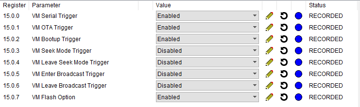
In general, most applications will only require the main function to be called at bootime to initialize peripherals and whenever the “VM execute” command is called. The triggering event can be fetched within the scripting environment by calling the GetExecType() function, which returns one of the values defined by macros of MESHEXECTYPE. You can find their definition in the SMK900.evi file. The next example presents a typical code structure used to determine the main function triggering event.
1 2 3 4 5 6 7 8 9 10 11 12 13 14 15 16 17 18 19 20 21 22 23 24 25 26 27 | #include "SMK900.evi"function execBoot(){/**boot up user code here*/}function execAirCmd(){/** VM execute user code here*/}function main(){ local execType; execType = GetExecType(); if(execType == MESHEXECTYPE_BOOTUP_bm){ execBoot(); } else if(execType == MESHEXECTYPE_AIRCMD_bm){ execAirCmd(); }} |
GPIOs
To topThere are three native functions to control GPIOs, namely: SetPinDir(pinID, dir),
SetPinOut(pinID, val) val = GetPinIn(pinID);
SetPinPull(pinID, enable). This function is used to activate pull-ups/pull-downs (40 kOhm). We choose either pull-up or pull-down with the last SetPinOut(pinID, val) all.
The following example uses these native GPIOs functions. At boot time, GPIOs 2 and 4 are respectively configured as input with pull-up and as output. Then, the value of GPIO 2 is read and written to GPIO 4 whenever the radio module receives a “VM execute” command.
1 2 3 4 5 6 7 8 9 10 11 12 13 14 15 16 17 18 19 20 21 22 23 24 | #include "SMK900.evi"function execBoot(){ SetPinDir(2,0); SetPinPull(2,1); //Enable the GPIO pull register SetPinOut(2,1); // Set the pull to pull-up SetPinDir(4,1);}function execAirCmd(){ SetPinOut(4,GetPinIn(2));}function main(){ local execType; execType = GetExecType(); if(execType == MESHEXECTYPE_BOOTUP_bm){ execBoot(); } else if(execType == MESHEXECTYPE_AIRCMD_bm){ execAirCmd(); }} |
The Buffer
To topThe virtual machine has access to a buffer containing 8 bits words and having a 100 bytes capacity. This buffer is being used to store RF packets received, to transmit RF packets, to read and write to registers and to store data from 32 bits mathematical operations. To write and read into this buffer, the next table summarizes the available native functions.
In order to write 16bits words into the buffer in little endian order, we call the transferUInt16ToReg(r,val) function. The latter can be found under the “util.evc” file that can be included in the header of the code.
1 2 3 4 | function transferUInt16ToReg(r, val){ SetBuffer(r,val&0xFF,1); SetBuffer(r+1,(val>>8) & 0xFF,1);} |
Send and Receive Data
To topVM codes can transmit and receive data from the mesh using the buffer. The native functions presented in the next table are available to the user to manipulate this data.
The code snippet shows how to echo VM execution through the serial port and through the mesh. The entire received dataset is sent back to the sender.
1 2 3 4 5 6 7 8 9 10 11 12 13 14 15 16 17 18 19 20 21 22 23 24 25 26 27 | #include "SMK900.evi"function execAirCmd(){ local count; count = GetAirBufCount()-1; GetAirBuf(0,1,count); Send(count);}function execSerialCmd(){ local count; count =GetTxBufCount()-1; GetTxBuf(0,1,count); Send(count);}function main() { local execType; execType = GetExecType(); if(execType == MESHEXECTYPE_AIRCMD_bm){ execAirCmd(); } else if(execType == MESHEXECTYPE_SERIAL_bm){ execSerialCmd(); }} |
Mathematical Operations
To topAll mathematical operations are encoded on 16 bits signed integers. Therefore we can use the generic operators as well as the binary operators as presented in the next table.
Table: Mathematical operations
To topIn some cases, we might also want to do mathematical operations on 32 bits signed integers. We then use the buffer native functions associated with 32 bits mathematical operations. Each function considers that numbers are encoded into 32 bits in little endian order and in 4 buffer slots. Thus, to insert a 32 bits number into our buffer, we include the “util.evc” file (#include “util.evc”) et call one of the following functions.
1 2 3 4 5 6 7 8 9 10 11 12 13 14 15 16 | function transferUInt16ToReg(r, val){ SetBuffer(r,val&0xFF,1); SetBuffer(r+1,(val>>8) & 0xFF,1); }function transferUInt16ToUInt32(r, val){ SetBuffer(r,0x00,4); transferUInt16ToReg(r, val);}function transferBytesManuallyToUInt32(r, lsbyte0, byte1, byte2, msbyte3){ SetBuffer(r,lsbyte0&0xFF,1); SetBuffer(r+1,byte1&0xFF,1); SetBuffer(r+2,byte2&0xFF,1); SetBuffer(r+3,msbyte3&0xFF,1);} |
The native functions in Table are used to handle mathematical operations. Their results are directly stored in the buffer.
Since we can only do mathematical operations on integers, we add a multiplying factor to handle floating point numbers. For example we can multiply an integer by 100 to simulate a number with two decimal places. Example ~\ref{listing:handlingfloatingpointnumbers} shows how we can use mathematical operations in a VM code to compute the following equation:
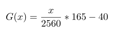
1 2 3 4 5 6 7 8 9 10 11 12 13 14 15 16 17 | #include "SMK900.evi"#include "util.evc"{/* function g store the result of G(x) in the buffer at the index r with a scaling of 100.The data at index [r+4,r+7] will be overwritten during the operation.*/function g(r,x){ transferUInt16ToUInt32(r,x); transferUInt16ToUInt32(r+4,165*100); MulBuffer_S32(r,r+4); transferUInt16ToUInt32(r+4,2560); DivBuffer_S32(r,r+4); transferUInt16ToUInt32(r+4,40*100); InvBuffer_S32(r+4); AddBuffer_32(r,r+4);} |
As we can see in the previous example, when function G(0, 2000) is called, the buffer content after the function execution will be the as show in the next table.
The 32 bits value in the buffer is 0x22ba or 8890. Taking into account the 100 multiplying factor, we find the floating point result as 88.90 which is a closed enough approximation of the real calculated value [G(2000) = 88.90625].
The inherent truncation that occurs when handling numbers with integers can be mitigated by increasing scaling.
Time Functions and Constraints
To topWhen the VM is triggered by a VM execute command, it will then be executed during the sleep cycle of the SMK900, between two LED blinks (remember that the radio module blinks when the module is awake and transmitting/receiving). Because of this, we have to make sure that the VM code runs within a timeframe shorter than the sleep cycle. The sleep duration can be calculated from the DYN parameters.
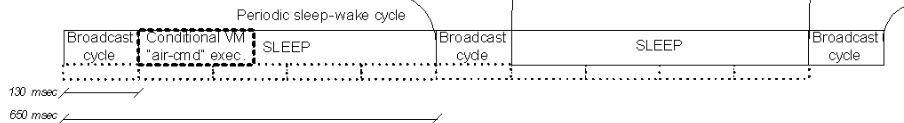
Most functions can be executed in a timely fashion and wouldn’t impact on the mesh operation unless there are long loops. However, there is one native function, the Delay(time) function, that has to be used with great care and we should always keep in mind the inherent time constraint of the VM execution when using it.
There are also non-native functions available to get a few important time values. These functions can be found under the “timing.evc” file and are presented in the next table.
The next example shows a delay implementation using getTime_ms() and Delay(time) functions. Note that with Delay(time) the code will be hanging and we can’t run any other operation while waiting. Whereas, getTime_ms() allows us to continue other operations during this waiting time.
1 2 3 4 5 6 7 8 9 10 11 12 13 14 15 16 17 18 19 20 21 22 23 24 25 26 27 28 29 30 31 32 | #include "SMK900.evi"#include "timing.evc"function execBoot(){ SetPinDir(4,1); SetPinOut(4,0);}function execAirCmd(){ local stampTime; SetPinOut(4,1); stampTime = getTime_ms(); while(getTime_ms() < (stampTime + 200)){ //Do something while waiting here } SetPinOut(4,0); Delay(2000);//200 ms SetPinOut(4,1); Delay(2000); SetPinOut(4,0); }function main(){ local execType; execType = GetExecType(); if(execType == MESHEXECTYPE_BOOTUP_bm){ execBoot(); } else if ((execType == MESHEXECTYPE_AIRCMD_bm) || (execType == MESHEXECTYPE_SERIAL_bm)) { execAirCmd(); }} |
Reading and Writing Registers
To topThe radio module holds an image of the registers at three different places: in the EEPROM, the RAM and the RAMBUF. At bootime, the copy in the EEPROM is copied into the RAM and then into RAMBUF. The main Portia (SMK900) program uses the RAM registers copy. EEPROM copy is used to store register configurations persistantly. Then, there’s the RAMBUF copy which is used as a memory buffer to allow simultaneous writing operations into the registers stored in the EEPROM. Thus, in order to write into a register stored in the RAM or EEPROM, we have to first modify the registers stored in RAMBUF. Then, we transfer the RAMBUF content into the RAM or EEPROM.
The Portia module contains many registers which are detailed here. All of these registers can be read and modified in the config tab of SpiderMeshIDE. We can also read and write into these same registers through our VM code. Table list the native functions to manipulate these registers.
Writing Registers to EEPROM
To topThe next example code uses the register read and write functions in order to change nwkid and hoptable registers stored in the EEPROM. Since we cannot continuously write to the EEPROM, the code first reads the value and check whether we have to update it or not. Then, writing into the EEPROM is done in three steps:
- We write the registers to RAMBUF
- We transfer the content from RAMBUF into EEPROM
- We reset the radio module to apply changes
1 2 3 4 5 6 7 8 9 10 11 12 13 14 15 16 17 18 19 20 21 22 23 24 25 26 27 28 29 30 31 32 33 34 35 36 37 38 39 40 | #include"SMK900.evi"function execBoot(){ local hopTable; local nwkid; local hopTableEEPROM; local nwkidEEPROM; hopTable = 2; nwkid = 5; GetRegisterEEPROM(0, REGISTER_NWKID); GetRegisterEEPROM(1, REGISTER_HOPTABLE); nwkidEEPROM = GetBuffer_U8(0); hopTableEEPROM = GetBuffer_U8(1); if( nwkid != nwkidEEPROM || hopTable != hopTableEEPROM){ SetBuffer(0,nwkid,1); SetBuffer(1,hopTable,1); SetRegisterRAMBUF(0, REGISTER_NWKID); SetRegisterRAMBUF(1, REGISTER_HOPTABLE); TransferConfigEEPROM(); while(1){ //Let watchdog kill the process } }}function main(){ local execType; execType = GetExecType(); if(execType==MESHEXECTYPE_BOOTUP_bm){ execBoot(); } else if(execType==MESHEXECTYPE_AIRCMD_bm || execType == MESHEXECTYPE_SERIAL_bm){ //User Code here }} |
Persistant Memory Between VM Executions
To topThe registers read/write function can also be used to store persistant information into global purpose storage (GPStorage) between VM executions. This is useful because all our global and local variables are reinitialized at every VM execution.
There are three GPStorage registers, each holding 8 bytes, for a total of 24 bytes. The next example counts the number of VM executions since bootime by stocking the vmCount variable into GPStorage_0 register.
1 2 3 4 5 6 7 8 9 10 11 12 13 14 15 16 17 18 19 20 21 22 | #include"SMK900.evi"function main(){ local execType; local vmCount; execType = GetExecType(); if(execType==MESHEXECTYPE_BOOTUP_bm){ vmCount = 0; SetBuffer(0,vmCount,1); SetRegisterRAMBUF(0,REGISTER_GPSTORAGE_0); } else if(execType==MESHEXECTYPE_AIRCMD_bm || execType == MESHEXECTYPE_SERIAL_bm){ GetRegisterRAMBUF(0,REGISTER_GPSTORAGE_0); vmCount = GetBuffer_U8(0); vmCount += 1; SetBuffer(0,vmCount,1); SetRegisterRAMBUF(0,REGISTER_GPSTORAGE_0); Send(1); }} |
The I2C Module
To topThe I2C module is normally configured as “master” and we cannot change it into slave because the I2C bus is being used to communicate with the coprocessor. The next table lists the available I2C native functions.
The next example shows the I2C bus use. We read a 10 bits value of the ADC (a MSP3021). The 7 bits I2C address of this sensor is 0x4D. The read and write addresses are respectively 0x9B and 0x9A.
1 2 3 4 5 6 7 8 9 10 11 12 13 14 15 16 17 18 19 20 21 22 23 24 | #define ADDRESS_R 0x9B#define ADDRESS_W 0x9Afunction readADC(){ local lowbyte; local highbyte; local value; I2C_Start(ADDRESS_R); highbyte = I2C_ReadAck(); lowbyte = I2C_ReadNak(); I2C_Stop(); //The data red is encoded this way // Upper Data Byte // 0 | 0 | 0 | 0 | D9 | D8 |D7 | D6 // LowerDataByte // D5 | D4 | D3 | D3 | D1 | D0 | X | X highbyte &= 0x0F; lowbyte &= 0xfc; value = (lowbyte +(highbyte << 8))>>2; return value;} |
When interfacing with sensors, always read the datasheet carefully as the I2C write sequence command of each IC is different.
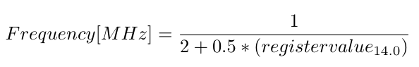
The default clock frequency is configured at 100 kHz. We can reduce this frequency by modifying register 14.0 (I2C clock speed). The clock frequency equation is:
Furthermore, one of the output pins of the Portia radio module is named I2C_PWR. Despite its name, it is not directly connected to the I2C port. Rather, it is a power output that can be used to power your circuits. The maximum DC current is 50 mA and it can be activated or deactivated using one of the functions listed in the next table.
SPI Integration
To topWith the current firmware version, the SPI uses bitbanging in order to act as a master. The SPI protocol is thus implemented with delay, GPIOs write, GPIOs read functions. The SPI Bitbang source code is found in the next example and can be included by adding #include “spi.evc” to the header
1 2 3 4 5 6 7 8 9 10 11 12 13 14 15 16 17 18 19 20 21 22 23 24 25 26 27 28 29 30 31 32 33 34 35 36 37 38 39 40 41 42 43 44 45 46 47 48 49 50 51 52 53 54 55 56 57 58 59 | #include "SMK900.evi"#define CS 7#define MOSI 8#define MISO 9#define SCK 10#define spi_start() SetPinOut(CS,0)#define spi_dly() Delay(2)function spi_stop(){ SetPinOut(MOSI,0); SetPinOut(SCK,0); spi_dly(); SetPinOut(CS,1); spi_dly(); SetPinOut(SCK,1); spi_dly(); SetPinOut(SCK,0);}function spi_write(value){ local i; for(i=0;i<8;i++){ if(value & 0x80){ SetPinOut(MOSI,1); } else{ SetPinOut(MOSI,0); } SetPinOut(SCK,0); value <<=1; spi_dly(); SetPinOut(SCK,1); } SetPinOut(MOSI,1);}function spi_read(){ local i; local out; out=0; for(i=0;i<8;i++){ SetPinOut(SCK,0); spi_dly(); SetPinOut(SCK,1); out <<=1; out += GetPinIn(MISO); } return out;}function spi_init(){ SetPinDir(CS,1); SetPinDir(SCK,1); SetPinDir(MOSI,1); SetPinDir(MISO,0); SetPinOut(CS,1); SetPinOut(MOSI,0); SetPinOut(SCK,0);} |
The following example shows how to implement the SPI protocol to our code.
1 2 3 4 5 6 7 8 9 10 11 12 13 14 15 16 | #include "spi.evc"#include "SMK900.evi"function main(){ local execType; execType = GetExecType(); if(execType==MESHEXECTYPE_BOOTUP_bm){ spi_init(); } else if(execType == MESHEXECTYPE_AIRCMD_bm){ spi_start(); spi_write(0x12); //write dummy value 0x12 on MOSI spi_stop(); Send(1); }} |
The ADC Module
To topThe SMK900 Portia radio module has a 12 bits ADC that can be read by the VM code. To do this, we need to Enable ADC register 38.0.0. We then can get the ADC reading with the AnalogRead(pinNumber) function. See the following table.
The following example reads the ADC of GPIO 4 and returns it though the mesh or the serial port.
1 2 3 4 5 6 7 8 9 10 11 12 13 14 15 16 17 18 19 20 21 | #include "refdes.evi"function transferUInt16ToReg(r, val){ SetBuffer(r,val&0xFF,1); SetBuffer(r+1,(val>>8) & 0xFF,1);}function execAirCmd(){ local adc; adc = AnalogRead(4); transferUInt16ToReg(0,adc); Send(2);}function main(){ local execType; if (execType == MESHEXECTYPE_AIRCMD_bm || execType == MESHEXECTYPE_SERIAL_bm){ execAirCmd(); }} |