Objective
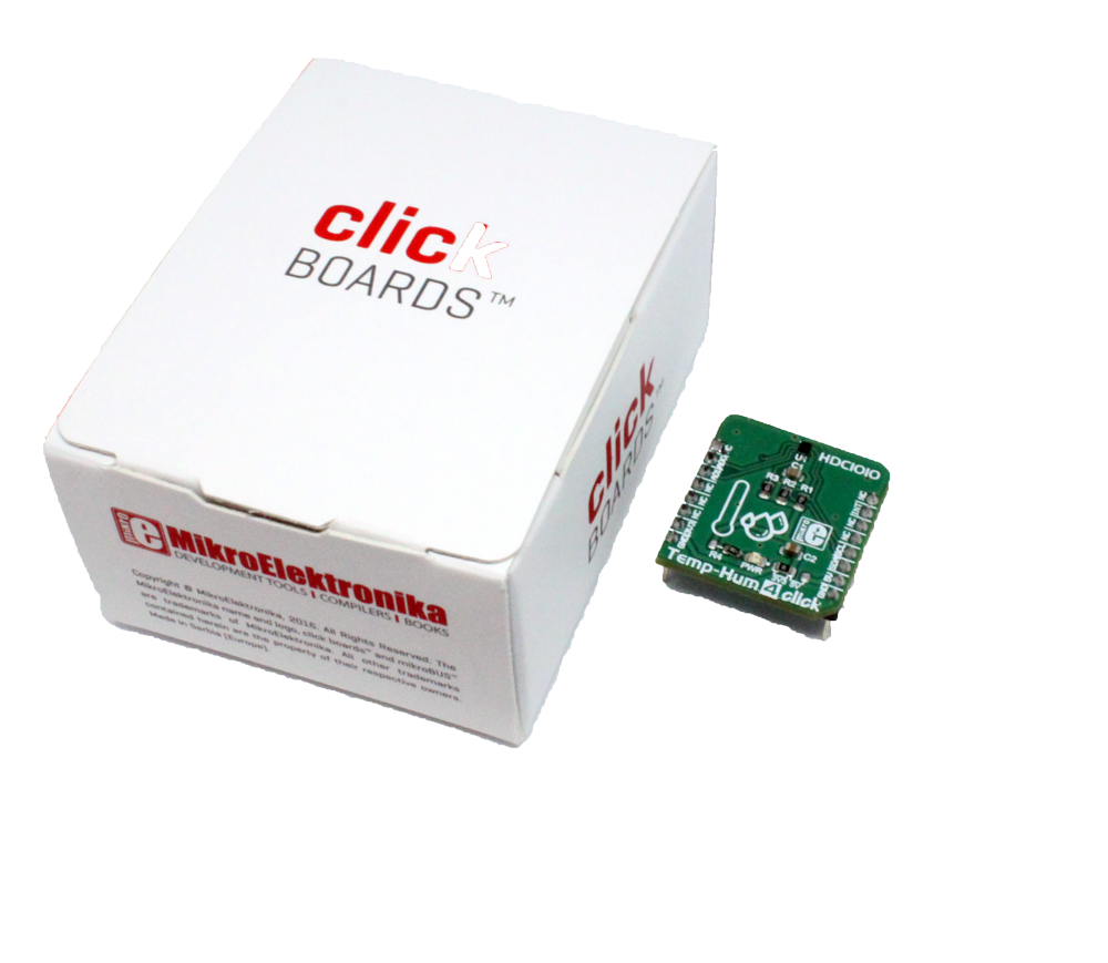
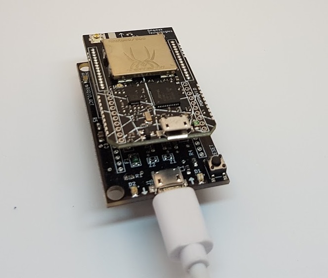
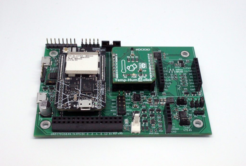
The objective of this tutorial is to gather data from a temperature and humidity sensor from a mesh network based on SMK-900. In this example, we use the HDC1010 sensor from Texas Instruments. It’s a low power sensor that offers highly accurate measurements. The chip that we use is mounted on a PCB from the MIKROE Click board series.
The materials that were needed for this tutorial
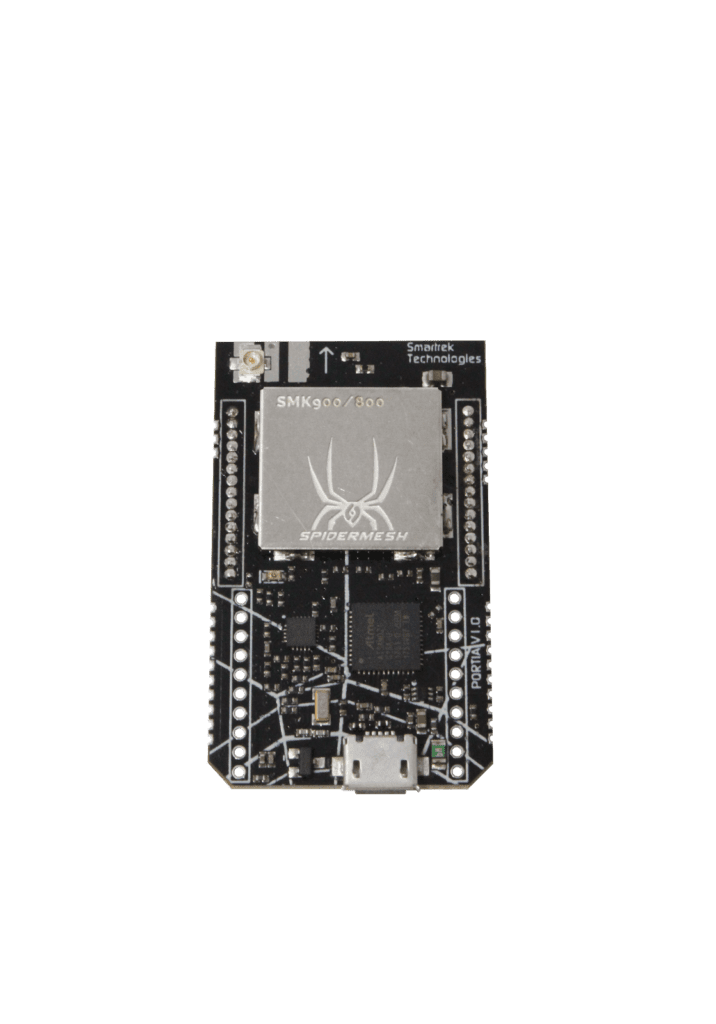
- 2 SMK-900 radios
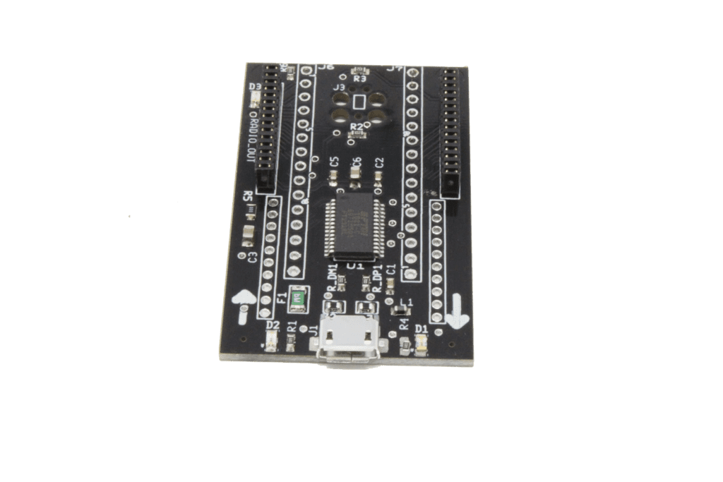
- 2 FTDI shield from Smartrek
- 1 Click Shield from Smartrek
- 1 Temp & Hum 4 Click Board from Mikroe
- 2 USB Micro Cables
- 2 Antennas
- The SpiderMesh IDE software
- 2 power supplies ranging from 3.3V to 5.5V (could also be a battery pack)
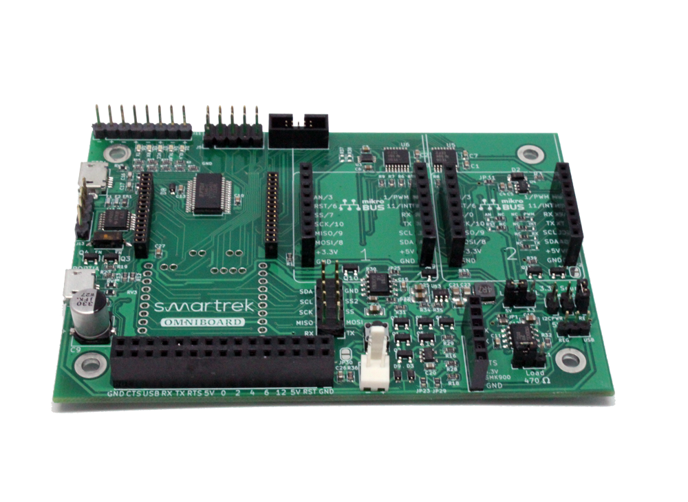


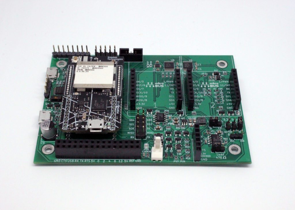
In order to make wiring easier, we’ll be using a Click Shield development board that you can get here. If you don’t have this board, then simply whip out the FTDI shield that’s provided with the development kit. You will then also need 4 additional female-to-female jumper wires for the connections.
Once you’ve gone through this tutorial, then you would have learned to:
- Create a new project with Spidermesh IDE
- Add radio modules to the project
- Configure a radio into a Gateway
- Configure a radio into a Node
- Synchronize Nodes with the Gateway
- Write your first EVM code
- Upload your VM code into your nodes
- Deploy a mesh on multiple hops
Starting a new SpiderMeshIDE project
Step 1
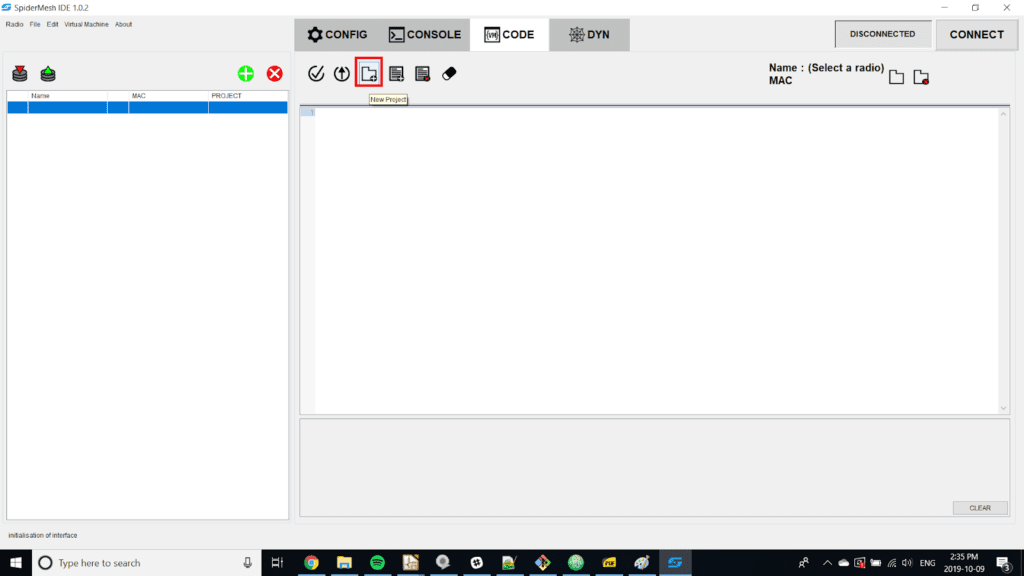
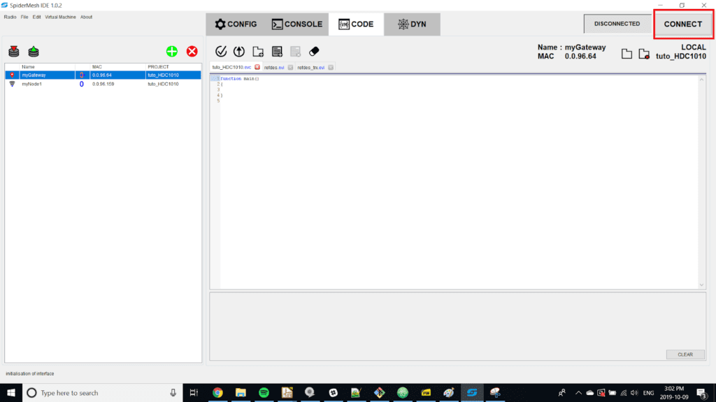
Open SpiderMesh IDE and go to the “Code” tab. Click on “New Project”. Name the project: tuto_HDC1010
Step 2
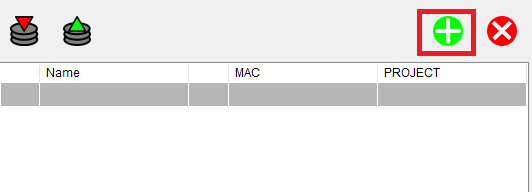
From the list of radios on the left, click on the “add a new radio”
Step 3
Fill in the following information for your radio
- Name: myGateway
- MAC: the MAC address of your radio that will be your Gateway (e.g. 0.0.96.64)
- Type: GATEWAY
- Project: tuto_HDC1010
- Location: LOCAL
Step 4
Next, add your second radio to the list and fill in the following information
- Name: myNode1
- MAC: the MAC address of your radio that will be connected to the temperature sensor (e. g. 0.0.96.159)
- Type: NODE
- Project: tuto_HDC1010
- Location: REMOTE
Step 5
Pin your Gateway radio module on the FTDI shield and connect the shield to your computer with the usb cable
Step 6
Click on “Connect” to open the serial port and connect to your radio. If the COM port of your radio is not detected, make sure that it’s the FTDI module that is connected to the usb port and not the SMK-900 module.
Step 7
Enter the following parameters for your serial port:
- Local serial port: The COM port of your gateway
- Baudrate: 115200
- Timeout: 10 sec
- Protocol: API
- Flow Control: CTS Enabled
Step 8
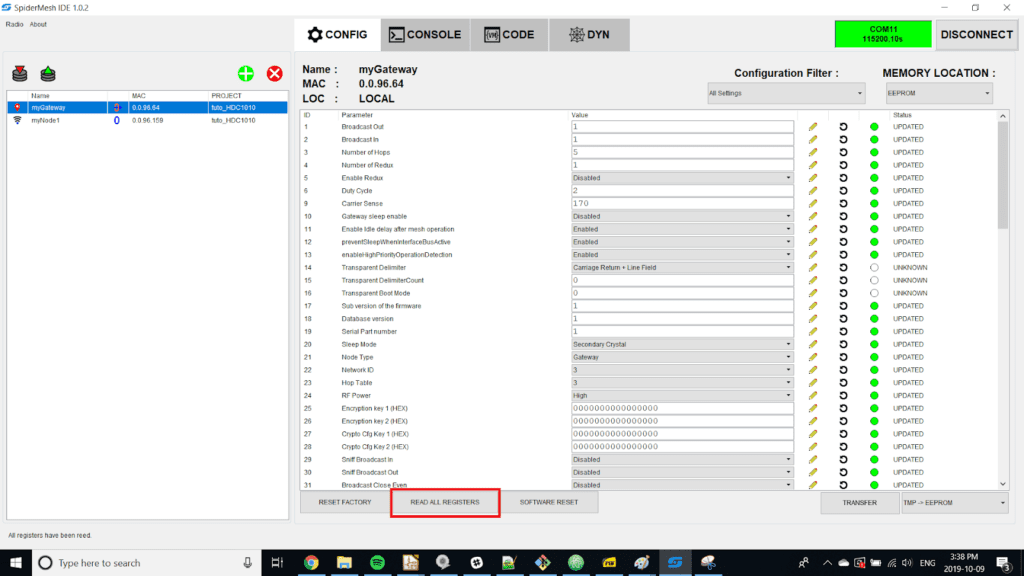
In the list of radios, click once on your gateway to select it. Then click the “config” tab then on ‘’read all registers’’. You should see the status of the registers as ‘’updated’’. If this is not the case, verify the following things:
- The “myGateway” radio is selected in the list.
- That the radio is configured as a “local” node and not as a “remote” node.
- You are connected to the correct COM port.
Step 9
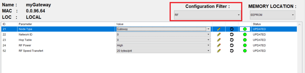
In the “Filter Configuration” section, select RF and modify the following parameters:
- Node Type: Gateway
- NetworkID: 0
- HopTable: 0
Step 10
On the right of the value, click on the pencil for each of the parameters that have been modified.
In this case, you will have to click on 3 different pencils.This will save changes to the registers in the temporary memory (RAMBUF) of the radio module. At this point, you should now see the “transfer” button blink which indicates that the modifications were made to the temporary memory.
Step 11
Click on the drop-down menu at the bottom right next to the “transfer” button and select “TMP -> EEPROM” (RAMBUF -> EEPROM) then click on the transfer button. The configuration will now be saved into the EEPROM of the radio module.
Step 12
Click on SOFTWARE RESET so the module can update its configuration.
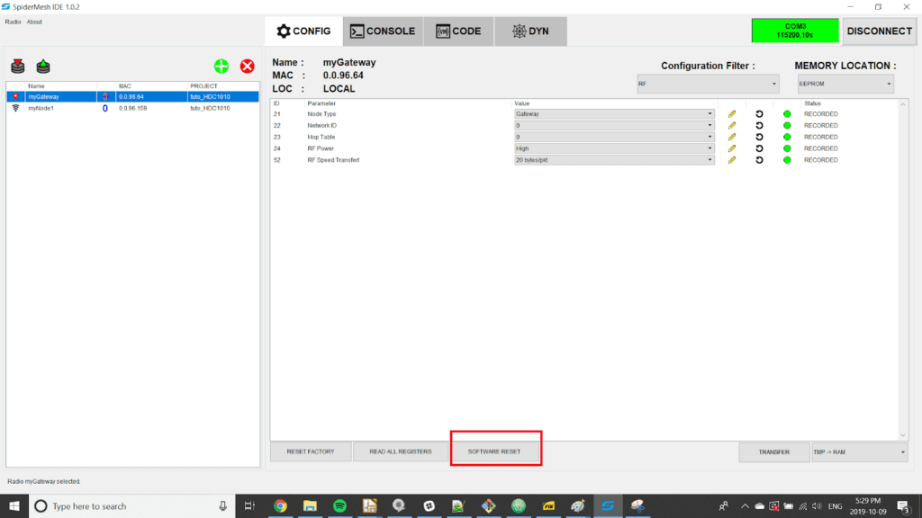
Step 13
Validate your modifications by clicking on “Read all registers”, your changes should be saved. Note that it is also possible to read one single register at a time by clicking on the circular arrow to the right of the pencil.
Step 14
Connect an antenna to your radio module.
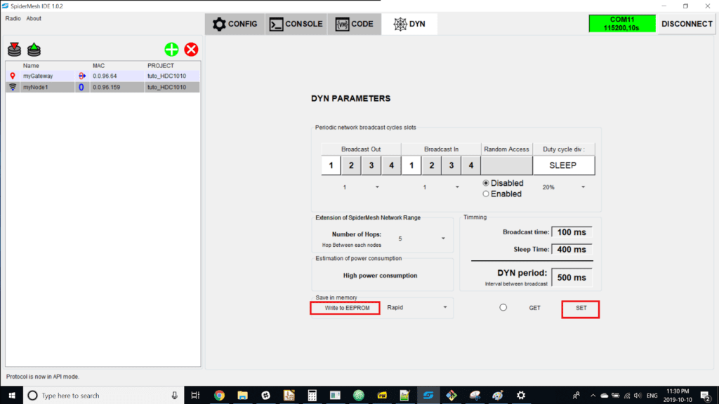
Step 15
Go to the “Dyn” tab and change the duty cycle of the network by entering the following parameters:
- Broadcast Out : 1
- Broadcast In : 1
- Random Access : disable
- Duty cycle div : 20 %
- number of Hops : 5
Step 16
Click on the “Set” button then click on “Write to EEPROM”.
Step 17
Install your second radio on the click shield, then connect the USB FTDI port to your computer. If you do not have this tool, install it on another FTDI module.
Step 18
Configure the “myNode1” radio as a “local” node instead of a “remote” node. In order to have access to the radio parameters, you will have to double click on the list of radios located on the left of the interface.
Step 19
Click on the button “disconnect” located at the top right. Then, connect the node by clicking on “connect”. Make sure to choose the COM port corresponding to your node and NOT the COM port of the gateway.
Step 20
Repeat steps 7 to 14 but choose the “myNode1” radio and change the “Node Type” parameter so that it has the value “Node”.
Step 21
After a few moments, the gateway and node LEDs should flash at the same time. This means that communication has been established and the node is syncing well with the gateway.
Writing the EVM Code
This section describes how to write the EVM code in order to operate the HDC1010 sensor with a node based on the SMK900. We’ll explain how to write the code through a step-by-step process. The completed code can be found at the end of this section.
Step 22
Firstly, you must include the file “refdes.evi” in your project to have access to all the native functions of the EVM code. This set of functions allows access to the different registers and buffers of the radio module.
#include "refdes.evi"

function main(){
	//to be continued...
}
Step 23
The main() function of the EVM code is triggered by different events. By default, it’s called at bootime, at the reception of a VM air command requests, at a serial port write event. In this case, the program will have to read the sensor on a VM air command.
The native function GetExecType() is used to determine the event that triggered the execution of the main() function. Therefore, you have to write the code to distinguish the different calls of this last function.
#include "refdes.evi"


//Command to be executed when the gateway sends an air command

function exec_aircmd(){
	//to be continued...
}

function main(){
	local execType;
	execType = GetExecType();
	if(execType==MESHEXECTYPE_AIRCMD_bm){
		exec_aircmd();
	}
}
Step 24
You then have to determine the variables that will be used in the program. The EVM language does not allow variable declaration later in the code, so they must be declared at the beginning of the function. In this case you will need a variable for the configuration, for the raw value of temperature and for the raw humidity value. These local variables are on 16 bits.
#include "refdes.evi"

//Command to be executed when the gateway sends an air command
function exec_aircmd(){
	//Variable for HDC1010
	local raw_temp;
	local raw_humidity;
	local config;
	//to be continued...
}

function main(){
	local execType;
	execType = GetExecType();
	if(execType==MESHEXECTYPE_AIRCMD_bm){
		exec_aircmd();
	}
}
Step 25
The next step is writing the correct sequence to fetch data on the I2C bus. For this sensor, the information can be found under section 8.5.2.3 of the HDC1010 datasheet. For this sequence, the I2C native functions must be used:
- I2C_Start(address)
- I2C_Stop()
- I2C_ReadAck()
- I2C_ReadNak()
Note that the address argument of the start function is on 8 bit, it includes the 7 address bits and the read/write bit.
According to the datasheet, you must perform the following steps in this order to take a measurement:
- Configure the acquisition parameters using the configuration register.
- Start a measurement by writing to the temperature register.
- Wait for the acquisition.
- Retrieve information.
To retrieve the values measured with I2C_ReadAck() and I2C_ReadNak(), you will need a table to store the read values. These are global and must be declared in the header of the project. The read functions of the I2C bus return 8-bit values. Note that it’s also possible to store the values of the I2C bus in a local variable instead of an array.
The acquisition code is the following:
#include "refdes.evi"
#define HDC1010_ADDRESS_W 0x80 // 7 bit adress = 0x40
#define HDC1010_ADDRESS_R 0x81
#define CONFIGURATION_REGISTER 0x02

array8u HDC1010_buffer[4];

//Command to be executed when the gateway sends an air command
function exec_aircmd(){

	//Variable for HDC1010
	local raw_temp;
	local raw_humidity;
	local config;

	//Write to configuration register
	config = 0x1000;
	// Temperature resolution = 14 bit
	// Humidity resolution = 14 bit
	// Heather is disable
	// Acquisition Mode is for Temperature
	// and humidity measurement

	I2C_Start(HDC1010_ADDRESS_W);
	I2C_Write(CONFIGURATION_REGISTER);
	I2C_Write((config & 0xff00)>>8);
	I2C_Write(config & 0xff);
	I2C_Stop();

	//Trigger Measurement
	I2C_Start(HDC1010_ADDRESS_W);
	I2C_Write(0x00);

	//Wait for measurement to be done
	Delay(1000); // Delay of 1000*100us = 100 ms

	//Acquire Data for temperature and humidity
	I2C_Start(HDC1010_ADDRESS_R);
	HDC1010_buffer[0] = I2C_ReadAck();
	HDC1010_buffer[1] = I2C_ReadAck();
	HDC1010_buffer[2] = I2C_ReadAck();
	HDC1010_buffer[3] = I2C_ReadAck();
	I2C_Stop();

	raw_temp = (HDC1010_buffer[0] << 8) + HDC1010_buffer[1];
	raw_humidity = (HDC1010_buffer[2] << 8) + HDC1010_buffer[3];

	//to be continued...
}

function main(){
	local execType;
	execType = GetExecType();
	if(execType==MESHEXECTYPE_AIRCMD_bm){
		exec_aircmd();
	}
}
Step 26
Once the data has been acquired, it must be sent back to the gateway. This is possible with the following two native functions:
- Send(length)
- SetBuffer(position,value,repetition)
To send a packet to the gateway, you must first fill in a buffer. In this case, it’s a native buffer of the radio module and not an array like the HDC1010_buffer.
This buffer is 256 bytes in size. To fill it, you’ll have to use the SetBuffer(position,value,repetition) function. The terms are defined below:
- position : The index to which the value will be written in the buffer
- value : the 8-bit value to write in the buffer
- repetition : the number of times the value is written on the board.
For example, if the SetBuffer(3,0xbe,3) function is used, the value 0xbe will be written in index 3, 4 and 5. The Send(length) function allows you to send the contents of the buffer. The length argument determines the number of bytes to send.
Note that the native operations on the buffer use the little Endian format. The complete code is shown below.
#include "refdes.evi"
#define HDC1010_ADDRESS_W 0x80 // 7 bit adress = 0x40
#define HDC1010_ADDRESS_R 0x81
#define CONFIGURATION_REGISTER 0x02

array8u HDC1010_buffer[4];

//Command to be executed when the gateway sends an air command
function exec_aircmd(){
	//Variable for HDC1010
	local raw_temp;
	local raw_humidity;
	local config;

	config = 0x1000;
	// Temperature resolution = 14 bit
	// Humidity resolution = 14 bit
	// Heather is disable
	// Acquisition Mode is for both measurement
	// at the same time

	I2C_Start(HDC1010_ADDRESS_W);
	I2C_Write(CONFIGURATION_REGISTER);
	I2C_Write((config & 0xff00)>>8);
	I2C_Write(config & 0xff);
	I2C_Stop();

	//Trigger Measurement
	I2C_Start(HDC1010_ADDRESS_W);
	I2C_Write(0x00);

	//Wait for measurement to be done
	Delay(1000); // Delay of 1000*100us = 100 ms


	//Acquire Data for temperature and humidity
	I2C_Start(HDC1010_ADDRESS_R);
	HDC1010_buffer[0] = I2C_ReadAck();
	HDC1010_buffer[1] = I2C_ReadAck();
	HDC1010_buffer[2] = I2C_ReadAck();
	HDC1010_buffer[3] = I2C_ReadAck();
	I2C_Stop();

	raw_temp = (HDC1010_buffer[0] << 8) + HDC1010_buffer[1];
	raw_humidity = (HDC1010_buffer[2] << 8) + HDC1010_buffer[3];

	//Filling the buffer with the data

	SetBuffer(0,raw_temp & 0xFF,1);
	SetBuffer(1,(raw_temp >> 8) & 0xFF,1);
	SetBuffer(2,raw_humidity & 0xFF,1);
	SetBuffer(3,(raw_humidity >> 8) & 0xFF,1);

	Send(4);
}

function main(){
	local execType;
	execType = GetExecType();
	if(execType==MESHEXECTYPE_AIRCMD_bm){
		exec_aircmd();
	}
}
Programming The Module
Step 27
Connect your radio or your gateway to your computer’s serial port. If you are connected to your gateway, the programming is done over the air, if not it’s via the FTDI module.
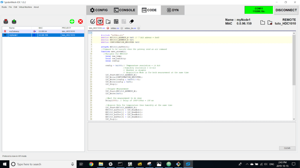
Step 28
Select the “myNode1” radio in the list of radios.
Step 29
Click on the button “compile and upload”. The results will appear in the console under the text editor.
Reading The Temperature Measurement On The Console
Step 30
Connect the click board to the mikroe bus # 1 of the click shield and install the jumper power supply to the following way:
- LEVEL SEL: 3.3 V
- 3.3V Source : SMK900
Step 31
Go to the console tab and in the frame type drop-down menu, select “VM execute command” and in “Mode” select “API”.
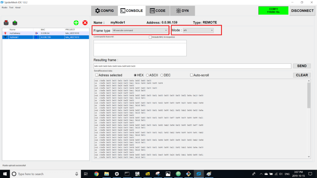
Step 32
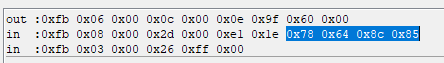
Make sure that the node is synchronized with the gateway then click on the clear button then click send. The transmission is then displayed in the console.
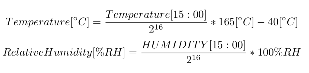
Step 33
In this case, the value on 16 bits of the temperature is 0x6478 and the raw humidity value is 0x858c. By using the equations found in section 8.6.1 et 8.6.2 of the HDC1010 datasheet, you can determine that the actual temperature is 24.755 °C and the humidity 52.16 %.