Overview
This is a review of some design guidelines and some pitfalls to avoid for the host to gateway communication with SpiderMesh
SpiderMesh is a self-configuring and self-healing wireless protocol. It takes care of the end nodes and gateway synchronization for you. However, in order to control this network, you have to:
- Choose a host and the link type to the gateway
- Develop your own application to talk to the network
- Choose and implement a communication scheme for the host to talk to the gateway
There are three ways that a host (laptop, personal computer, server, etc.) can communicate with a gateway. Using one of these communication schemes, a single gateway can access all nodes connected to its own mesh network, and therefore a host cannot reach out to the rest of the network without a gateway bridging RF communication to the serial bus.
Here, we’ll cover 3 communication methods:
- handshaking,
- periodic marker,
- on-demand marker.
Audience
This documentation is designed for people familiar with SpiderMesh implementation as well as the requirements to implement serial communication. You should also be familiar with computer hardware and operating system latency concepts. There are many serial communication tutorials available on the Web.
This conceptual documentation is designed to help you start developing the host to gateway serial communication part of your application. It covers all the possible ways that you can exchange data with a gateway.
A Quick Reminder
A system usually has:
- A host (embedded computer, laptop, server, etc.)
- A gateway
- One or several end nodes scattered into a mesh network
When a host exchanges data with a gateway, the messages are called local packets.
When data is sent on the mesh network to the end nodes, the messages are called over-the-air packets.
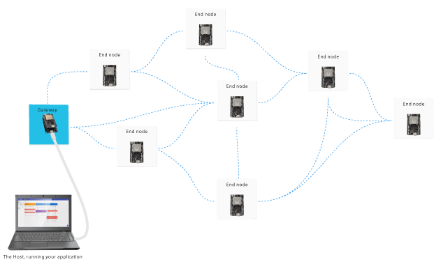
You can choose to connect the host to the gateway using one of these two methods:
- On the serial port, using an FTDI USB adapter board, or directly with serial 3.3V TTL;
- Over Bluetooth via an RFCOMM serial bridge
The One-at-a-time Rule
When developing your application on the host machine, keep in mind the following one-at-a-time rule to ensure proper communication over the mesh network:
- The gateway can only receive one over-the-air-packet per broadcast cycle per phase from the host;
- The gateway can only receive one over-the-air-packet per broadcast cycle per phase from the nodes.
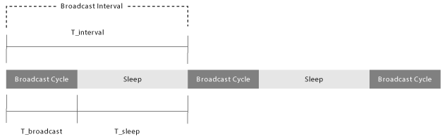
Remember that a broadcast cycle is
- The period where a gateway and its synchronized nodes communicate back-and-forth with each other.
Between two broadcast cycles, there is
- a sleep period where the nodes either sleep or process their request at leisure and fetch/control their locally-connected sensors
The broadcast interval is defined as both the broadcast cycle and the sleep period, combined.
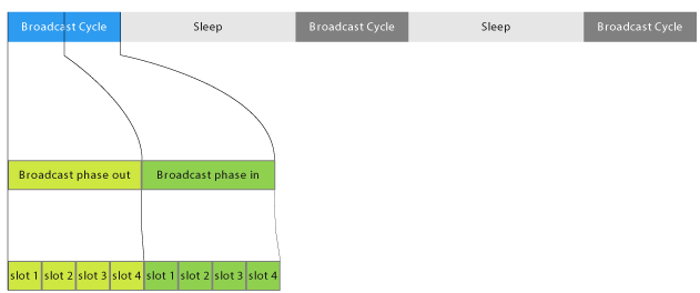
Moreover, each broadcast cycle has up to 4 phases in and 4 phases out. The number of phases in and out is configured in the mesh network dynamic (dyn) parameter.
Note that this rule only applies to packets that are to be transmitted over-the-air. Therefore, you can still send several local packets from your host to the gateway without breaking the one-at-a-time rule.
1st Method – Handshaking
If you are looking for simplicity and do not have any node-polling speed requirements, then your application should use handshaking in order to exchange data with the gateway. Handshaking can be used no matter the interface (transparent or API).
Using this method, your application instructs the gateway to send a message over-the-air. Then, no more over-the-air action is taken until either:
- An answer has been returned from the end node(s)
- 3 broadcast cycles have elapsed without receiving an answer from the end node(s) (The answer is expected from the node within 2 broadcast cycles, therefore the timeout should correspond to 2x broadcast interval + jitter, hence 3 broadcast cycles)
Therefore, reattempting communication over-the-air should only be done once one of these conditions has been met.
Pros
- Simple to implement
- Works well for a quick prototype
- Reliable
- Does not require packet identification
Cons
- Slowest method of node polling
- Does not leverage the full potential of the mesh speed
This method is simple and reliable, but it does not leverage the full potential of the mesh network in terms of speed. In addition, the periodic and on-demand methods that are covered in the following sections will increase node-polling speed but are harder to implement.
The End of Broadcast Marker
In the previous section, we’ve seen the handshaking method which is a suboptimal but simple communication scheme. In order to increase this speed, you can continuously have the host send requests for data to the end nodes without waiting for the answers to arrive beforehand.
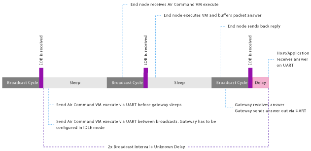
In order to do so and without violating the one-at-a-time rule, you will need some kind of knowledge on the current broadcast-cycle state so that your requests can be synchronized. This intelligence is provided by an optional End Of Broadcast (EOB) marker that can be sent periodically or on-demand (we’ll cover the on-demand EOB in the next section).
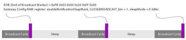
The End of Broadcast (EOB) marker is a predefined packet (0xFB 0x03 0x00 0x26 0xFF 0x00) that is sent by the gateway to the host, at the end of the active communication broadcast period (and thus, at the start of a sleep interval where non-critical operations are executed), to let your application know that the gateway is now ready to receive data.
To choose whether the EOB markers should be sent out on-demand, periodically or not all, configure register 17 of the SMK-900 module of the gateway.
The full registers list can be found here
Once you’ve received the EOB marker, and provided that it was received in a timely manner (see next section on the timing restrictions), your application should send out a new request message to the gateway, as fast as possible. The concept of timely EOB marker reception is critical for this method to work. As outlined before, you must ensure that the one-at-a-time rule is followed at all times.
This allows the optimization of the data exchange rate. An end node takes more than one broadcast cycle to process a message and send a reply, hence why there are 3 broadcast cycles waiting time from the handshaking method.
2nd Method – Periodic Marker
As mentioned before, the maximum mesh network speed can be achieved when communication between the gateway and the host is synchronized using EOB markers. With periodic EOB markers, you can time your software onto the heartbeat of the mesh.
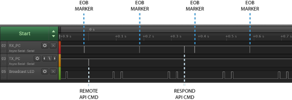
The following diagram shows 4 data exchanges on a simple mesh network. Note that there is an EOB marker for each cycle. Data is received in the order that it was originally sent by the host.
Timing Restriction
Packets are sent out periodically by the gateway when using the periodic marker communication scheme. These packets have to be continuously parsed by the host. While this communication scheme has proven to effectively speed up communication by a factor in many dedicated systems, there are some inherent implementation difficulties that cannot be overlooked.
Host devices, such as personal computers, laptops or servers can run multiple applications simultaneously with unexpected slowdowns from time to time. The delays that can occur with a heavy system load have to be properly assessed and managed in order to avoid the accumulation of consecutive EOB packets in the receiving hardware buffer, which can result in unpredictable behavior.
For instance, if somehow multiple EOB packets are found in the buffer, the serial port algorithm may think it can send multiple over-the-air-packet right away. If not managed appropriately, the one-at-a-time rule will be broken, which results in dropped messages. As highlighted before, this is a prohibited action that can yield unexpected results.
Pros
- Leverages the full mesh speed
Cons
- Difficult to implement
- Harder to keep track of the requests/answers (requires packet identification)
- Reliability heavily depends on implementation (skewed timing can occur when there is an unexpected computer slowdown)
3rd Method – On-Demand Marker
A third method has been implemented in order to alleviate the failure modes described above, in the timing restrictions section. Similarly to the periodic marker method, the on-demand marker method will also allow reaching the theoretical maximum mesh network speed.
A simple fail-safe mechanism avoids the unpredictable behavior issues when strict synchronization between host and gateway is not enforced with 100% reliability. It is a simpler implementation of the periodic marker method that removes the timing restriction of the host while maintaining the same speed.
In this specific mode of operation, the EOB markers are not sent automatically to host from a gateway, but rather are only sent after specific triggers initiated by the host. In this way, if your application or the host machine lags behind in some way, then the gateway will follow accordingly without filling the serial buffer with EOB messages.
Since there are no EOB markers automatically sent by the gateway, you are responsible to send the first over-the-air-packet request. This will automatically trigger the on-demand marker as soon as the gateway is ready to receive the next over-the-air-packet request. Using this scheme, one EOB marker per over-the-air-packet is sent back by the gateway, and there are no risks of buffer overflow, and there is no periodic EOB marker transmission.
However, in the case where you are able to send an over-the-air-packet in a timely fashion (as fast as possible) upon reception of an EOB marker, then the behavior over the serial bus is indistinguishable from the previous periodic method. This can be seen in the following bus recording screenshot. As demonstrated in the following logic analyzer bus capture, whenever your software or host machine is busy performing other tasks, it can simply skip a broadcast cycle without breaking the communication rules.
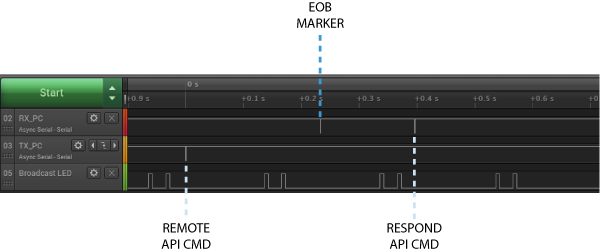
The following diagram shows 3 data exchanges on a simple mesh network. It should be noted that the end of broadcast markers are only present after a packet over the air is sent. The data is received in the same order as it was sent by the host.
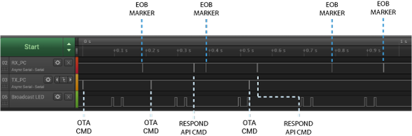
In the following serial bus signal capture using the on-demand marker method, we can observe that the host is lagging behind the mesh network broadcast cycle time. Unlike the previous example, with the implementation of the periodic marker, the EOB marker is not being sent out. The host may skip broadcast cycles and operate normally.
Pros
- Leverages the full mesh speed
- Easier to implement compared to the periodic marker method
- Reliability is less dependant on the implementation
Cons
- Harder to keep track of the requests/answers (requires packet identification)
Algorithm
When designing your software, you’ll need to reach out to every end node on the network periodically. To do so, your algorithm will be using some kind of queue list system to poll the network at regular intervals while taking into account the one-at-a-time rule. Here are some algorithm examples for each host-to-gateway communication method.
Some good practice guidelines to keep in mind
- Separate the host-to-gateway communication logic into its own separate thread
- The host-to-gateway communication logic should never be in the UI thread
- Implement yield period so that other threads and processes can run when there is no message queued. Furthermore, in order to achieve maximal network speed, you should yield less than 1/10 of the broadcast cycle time.
- When a multithreaded application is not possible, simulate multithreading with a state machine that is called rapidly from the main loop.
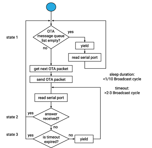
Handshaking
Implementing the handshaking method is the easiest way to go. Simply grab and send the first queued message then wait for the reply. The next message can then be sent whenever the reply has been received or when a timeout has been reached.
Remember that this timeout has to last at least 2 broadcast intervals to avoid breaking the one-at-a-time rule. Here’s how you should implement handshaking:
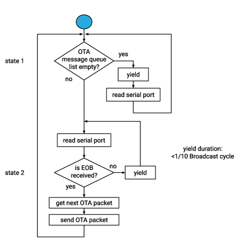
Periodic marker
The implementation of the periodic marker method is harder than the handshaking method because of the strict timing requirement. Since there are periodic EOB packets sent out to you, your system has to parse messages in a timely manner, even when nothing is scheduled to be sent out. Here’s how you should implement the periodic marker communication method:
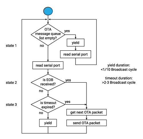
On-demand marker
The implementation of the on-demand marker method is basically the combination of the two previous algorithms. Therefore, additional EOB packets have to be parsed and a timeout also has to be implemented. This way, whenever the yield time stretches out of the broadcast interval (for example, when the processor is busy finishing other tasks), the next broadcast cycle will simply be ignored. Finally, with this method, make sure to send out the first outbound message in order to initiate data exchange with the on-demand EOB markers. Here’s how your communication algorithm should look like:
Identifying the Source of an End Node Packet
We’ve seen many ways to follow the communication rules of the SpiderMesh network. However, as outlined before, the implementation of faster communication methods is far more complex than the handshaking method because of the tight timing requirements. Moreover, polling multiple nodes without waiting for their answers requires you to keep track of what was sent and what was received.
Most of the time your application will send remote execute commands to a specific node in the mesh network and you’ll want to know whether a received reply came from that node or not. In order to identify the response from that addressed node, you have to embed a request for the sender address when generating the execute command frame.
The end node is going to receive and parse your execute command, do some processing (such as executing a script, polling a local sensor, etc.) and will embed its own address into the response frame. This way, you can discriminate which response came from which node easily. Usually, the received messages follow the node queries order. Nevertheless, keeping track of the origin of the received packets helps maintain a deterministic network and to confirm that there is no desynchronization.