Objective
- Learn the basics concepts of the SpiderMesh network
- Configure your radio modules to create a mesh network
Configuration Example
The following example shows the steps to synchronize a 6 hops mesh using a gateway and 4 nodes (5 SMK900 radio modules)
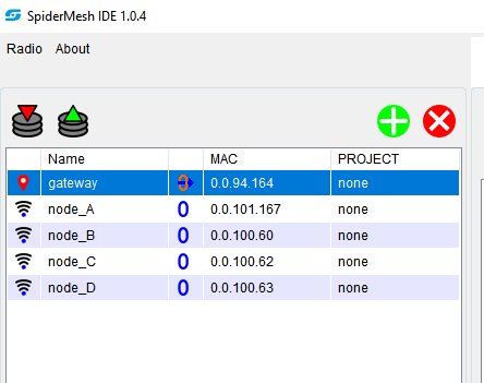
Step 1: In the radios list of the SpiderMeshIDE, add all 5 radio modules that will be used to create the
mesh network. Click on the button. Make sure to enter the correct MAC address that can
be found on the label on the shield of the radio module.
Time needed: 10 minutes.
The following example shows the steps to synchronize a 6 hops mesh using a gateway and 4 nodes (5 SMK900 radio modules)
-
In the radios list of the SpiderMesh IDE, add all 5 radio modules that will be used to create the mesh network. Click on the button. Make sure to enter the correct MAC address that can be found on the label on the shield of the radio module.

-
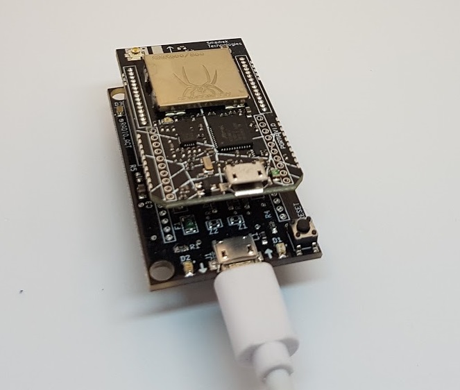
Connect the radio module to be configured as a gateway to the FTDI board
-
Install an antenna onto the module
-
Connect the FTDI board to your computer. Make sure to conenct the USB cable onto the usb port of the FTDI board and NOT the usb port of the SMK900 radio module.
-
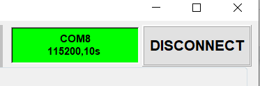
Open the serial port from SpiderMeshIDE by clicking on the Connect button which will turn green once the connection has been successfully established.
-
In the radios list, configure the gateway to be read locally (”local”)
-
Go to the ”Config” tab
-
Select the gateway in the radios list
-
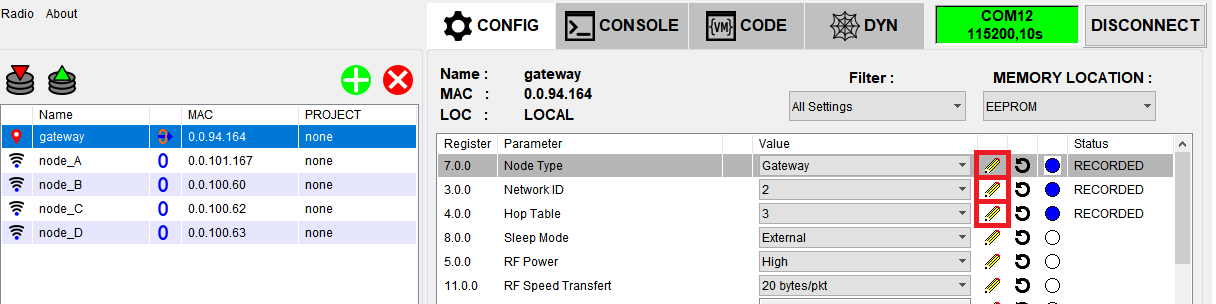
Modify the following registers:
— Node type: Gateway
— Network ID: Any number between 0 to 7
— Hop table: Any number between 0 to 5 -
For all three registers that we’ve configured at the previous step, click on the pencil button. If the values have been successfully written into the temporary buffer, then the ”Transfer” button should blink red.
-
Select TMP > EEPROM from the menu at the right of the ”Transfer” button in order to transfer the changes that we’ve made to the configurations into the EEPROM
-
Click on the ”Transfer” button to transfer the content of the temporary buffer into the EEPROM
-
Click on the ”Software Reset” button to apply the changes made. The yellow LED on the radio module should start blinking steadily indicating that the module is now configured as a gateway.
-
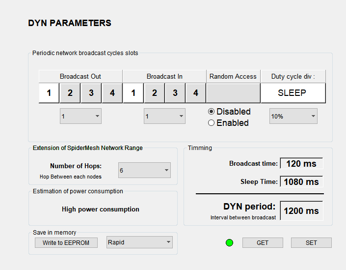
Go to the ”Dyn” tab
-
Change the ”Number of Hops” to 6
-
Change the duty cycle to increase or decrease the polling rate of the gateway (this can be seen by looking at the blinking rate of the LED on the gateway module). The resulting period from the duty cycle selection can be seen next to teh DYN period.
-
Click on ”Set” to change the configurations. If done properly, the LED next to GET seen on SpiderMeshIDE should turn green and the gateway module should change its blinking pattern accordingly.
-
Click on ”Write to EEPROM” to save these configuration for the next sessions (i.e. to keep the configurations when the gateway module will be restarted)
-
On another FTDI board, connect another radio module that will be configured as a node
-
Install an antenna on the radio module
-
Connect the FTDI board to your computer (remember to connect to the usb port of the FTDI board and NOT the radio module)
-
In the SpiderMeshIDE, click on ”Disconnect” to close the serial port and stop communicating to the gateway module
-
Connect SpiderMeshIDE to the new radio module, finding its COM port from your device manager
-
In the radios list, configure the radio module to communicate locally (select ”local”)
-
Go to the ”Config” tab
-
Select the radio module that we’ve just connected in the radios list
-
Modify its registers to the following:
— Node type: Node
— Network ID: The same value as we’ve previously set for the gateway
— Hop Table: The same value as we’ve previously set for the gateway -
Configure these three previous registers by clicking on the pencil button next to the register to be changed. You should see the ”Transfer” button blink red if you’ve successfully written to the temporary buffer
-
Select TMP > EEPROM from the menu at the right of the ”Transfer” button in order to transfer the changes that we’ve made to the configurations into the EEPROM
-
Click on the ”Transfer” button to transfer the content of the temporary buffer into the EEPROM
-
Click on the ”Software Reset” button to apply the changes made. The yellow LED on the radio module should start blinking steadily at the same pace as the gateway module after a few seconds to a minute. Your radio module is now configured properly as a node and connected
to the gateway. If the node does not start blinking with the gateway, check the configuration of both the node and the gateway for the Network ID and the Hop Table. These should match. -
Repeat steps 19 to 31 for each radio module to be configured as a node. You can use the same FTDI board to configure all nodes.
-
Power up all radio modules. After a few gateway blinks, all radio modules should start blinking
at the same pace. They are not forming a mesh network of 6 hops.
Understand the SpiderMesh Network
A SMK900 radio can be configured to operate in two main modes: gateway or node. A gateway controls a whole mesh network and functions as the main coordinator node, and its usual primary function is to bridge a host such as a PC, tablet, or internet gateway, with the rest of the mesh network.
A node is a transceiver that acts as a repeater inside of the mesh network. The primary function of a node is to allow communication between an external device and the gateway, or to serve as a bridge between analog and/or digital inputs/outputs such as for sensor arrays.
The topology used by a SMK900 radio is that of a broadcast-only mesh network, with sleep-wake synchronization handled by the gateway. This means that any SMK900 radio transmission sends a broadcast to the whole mesh network. The maximum of broadcast transmission of the same messages over the mesh network depends on the number of hops allowed.
Multiple independent mesh networks may coexist in the same physical space by configuring nodes with differing FHSS (frequency-hopping spread spectrum) channels, different network IDs and/or different encryption patterns. Each of those mesh networks have to be controlled by its own gateway.
The SMK900 uses the FHSS approach in order to ensure that co-located networks using different FHSS hopping tables (a.k.a channels) can coexist with graceful degradation of network performance as the number of conflicting networks overlapping increases. This however comes with the price that any node needs a certain time delay (called “seek time”) in order to connect itself to its desired network (this delay can range between seconds to minutes, depending on the sleep interval between wake cycles for said network. For instance, at a sleep interval of 1 second, the seek time is of the order of 30 seconds to 1 minute, and this seek time increases linearly with said sleep interval.
Every node also has a configurable network ID, called NWKID, between 0 and 7, which can be used to segregate multiple networks hopping on the same FHSS channel in order to reduce the impact of interference. Every node can also be encrypted using an unique network key, which not only secures a given mesh network, but also allows for more segregation between coexisting networks within the same physical space. The primary means for network segregation is of course the selection of the FHSS channel via a configuration variable named HOPTABLEID. The current implementation allows for values between 0 and 5 (i.e. 6 different hop tables).