Objective
This tutorial presents a summary of the SpiderMesh IDE features. After completing this tutorial you will be able to :
- Be familiar with the different functionalities of spidermesh IDE
- Configure the interface so that it communicates with all the radios in a mesh
- Connecting the interface to a radio via the serial port
- Read and write different radio registers of a mesh via the interface
- Change the packet sending frequency of a mesh.
- Programming the VM code of a radio via the serial port
- Programming the VM code of an OTA radio (”over the air”)
- Create a new VM project
The Interface
The tool used to program the radio modules is the Spidermesh IDE. It has an interface that allows you to modify all the key settings of the radio modules. This software lets you configure the different registers, develop the VM code and also has a communication interface with all the radios in the mesh.
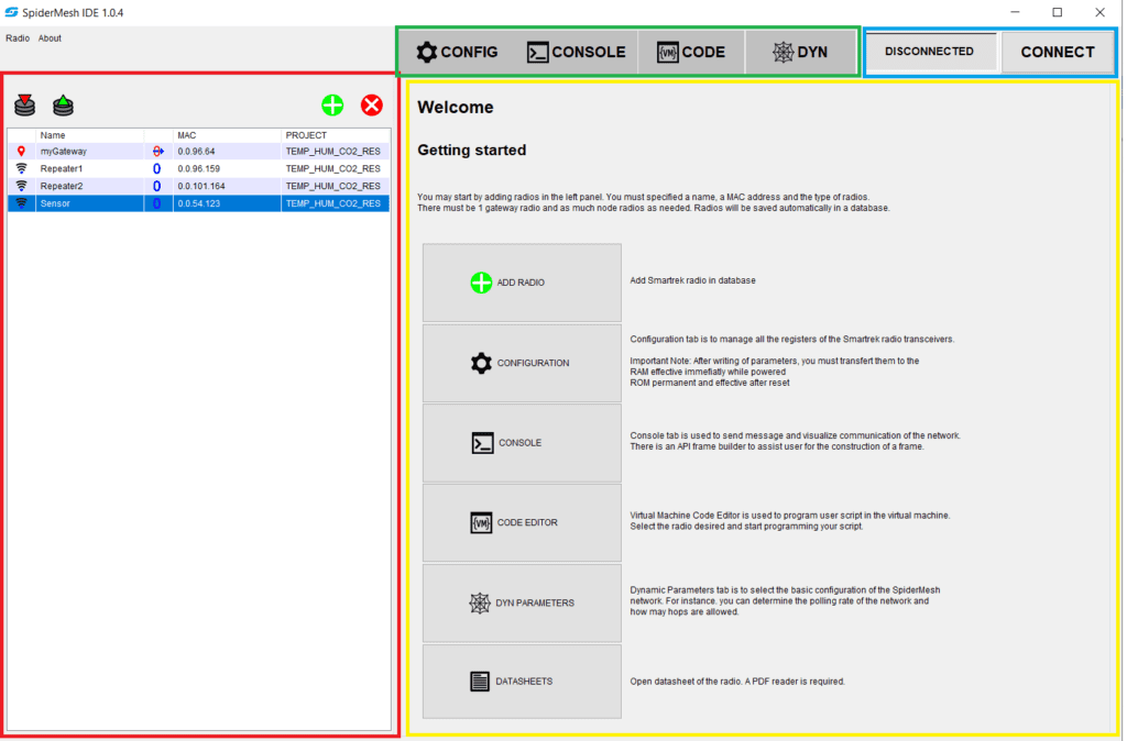
The following diagram shows the welcome interface of the Spidermesh IDE. On the left side the radio list in red, at the top are the 4 different tabs in green, and on the top right is the connection interface with the serial port in blue and in the center is the main window in yellow.
The Radios List
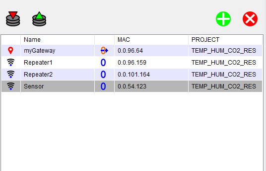
The radio list section allows you to select various radios in the mesh and send them certain commands. This section has 4 buttons:
 import a list of radios from a file with the .db extension.
- export a list of radios from a file with the .db extension.
- add a radio to the radio list.
- delete the selected radio from the radio list.
When the ![]() is clicked, a window will open and you will then be able to enter the radio’s information.
is clicked, a window will open and you will then be able to enter the radio’s information.
- Name: The name of the radio which is chosen by the user
- MAC address: this is found directly on the radio module
- Type: either a node or a gateway.
- Project: the VM project associated with this radio
- Location: either local or remote. When the radio is local, it must be connected with the serial port with a FTDI module. When it’s remote, it will be synchronized over the mesh and the commands are sent ‘’over the air’’.
When the radio module is added to the list, you will be able to see an overview of the settings. To make the process as easy as possible, the following symbols are used:
- Local
- Remote
- Gateway
- Node
Connecting a Radio
The serial port is used for the Spidemesh IDE software to communicate with the radio. To allow this, you must connect a radio module using either an FTDI board or a bluetooth gateway. In order to initiate the connection, the radio module must first be connected to an FTDI module and then connect the FTDI module to the computer’s USB port.
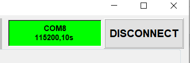
You must then click on the ‘’connect’’ button and fill out the information of the serial port.
- Local serial port: the serial port connected to the radio
- Baudrate: for an FTDI, the communication baud rate must be set to 115200, for a bluetooth module it must be 57600.
- Timeout: The maximum wait time to wait for an answer during a connection.
- Protocol: There are two modes, transparent or API. These are explained below.
- Flow control: Use the CTS pin assertion to synchronize the communication. Generally, using CTS Enable is more stable.
Once the connection is established, the serial port information will be displayed and will appear in green. If the connection fails, it will be displayed in yellow. In order for the software to communicate with the nodes as a whole in the mesh, it must be connected to a local gateway.
Transparent Mode
This protocol allows message broadcasting to all radios in the network. The gateway coordinates information exchanges in an invisible way while also acting as a node to send and receive messages.
Note: When powering up the radio, the communication protocol is in transparent mode. Then the software modifies this mode once the serial port is connected.
API Protocol
This protocol allows access to all the features of the SpiderMesh network. Communication between two points or to all nodes is then possible. In this mode, radio modules can be configured and Virtual Machine code can be uploaded.
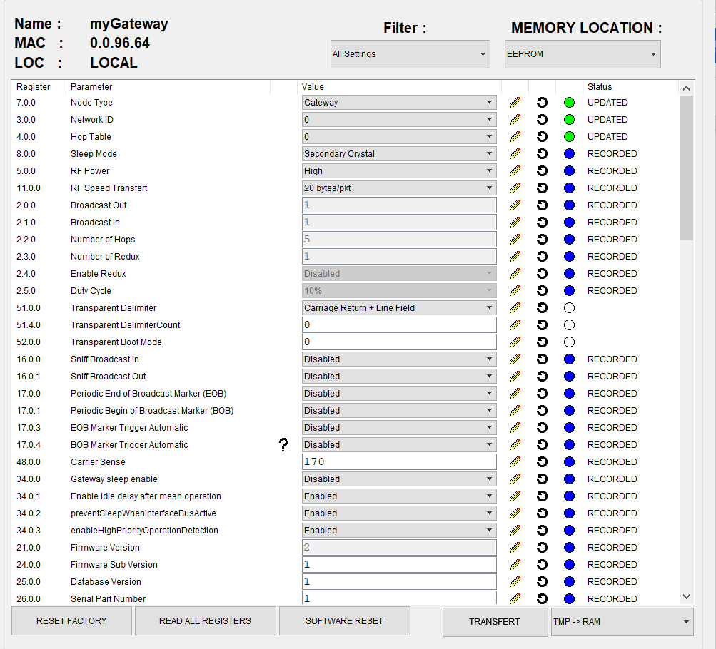
The Configuration Registers
The “CONFIG” tab gives you access to a radio register control interface. To select a radio, all you have to do is click on the desired radio from the list. The name, the MAC address and the ‘’location’’ will then be up to date in the config tab. There are hundreds of registers, therefore, in order to facilitate their configuration, you can filter the displayed registers so searching is made easier.
Before reading or writing a register, you have to connect to the mesh. There are two ways to do this. The first is connecting directly to the mesh on a local radio.The second way consists of connecting to a gateway that is also connected to a ‘’remote’’ radio via the mesh.
In the radio module, the registers can be stored in 3 different locations:
- EEPROM: The registers stored in EEPROM are loaded in RAM at each Boot.
- RAM: The registers in RAM are the ones used by the main program.
- RAMBUF: The registers in the RAMBUF can be changed from the serial port. This buffer can also be transferred to EEPROM and/or RAM using the “transfer” button.
The dropdown menu called ‘Memory Location’ allows you to choose in which of the last 3 memory locations the register readings are made. It’s possible to read each of the registers individually by clicking on \mychar{./res/TUTO_SPIIDE_OVERVIEW_refresh.png}. It’s also possible to read all the registers of a memory location using the “Read all register” button. The status of the register is defined by the color of the tablet:
- The value has recently been updated
- The value has been modified on the interface
- An error occurred when reading the register
- The value shown is the last value read by the application
- The value has not been read for this radio yet
You can also write to the registers of a radio easily using Spidermesh IDE. It is only possible to write directly into the RAMBUF. In order to write to RAM or EEPROM, you must first write to RAMBUF and then transfer the contents of the RAMBUF to either RAM or EEPROM.
For example, to modify a register in EEPROM via the serial port, you must follow these steps:
- Connect the application to the desired radio via an FTDI module.
- Select the radio from the list of radios.
- Configure the radio in local mode.
- Go into the config tab and select EEPROM from the dropdown menu of the memory location.
- In the dropdown menu on the bottom right, next to the “Transfer” button, select TMP ~> EEPROM.
- Modify the desired register’s value.
- Click on the \mychar{./res/TUTO_SPIIDE_OVERVIEW_pencil.png} on the right of the desired register. The “Transfer’’button should start blinking.
- Click on “transfer” to save the changes in EEPROM.
- Finally, click on software reset. When it starts rebooting, the radio will load the data from its EEPROM.
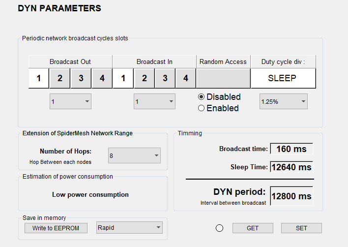
DYN
The DYN tab lets you easily modify certain registers, the “dynamics parameter”. These registers can’t be modified from the “config” tab. These settings are used when the radio module is configured in “gateway” mode to synchronize the packet send off.
There are 5 key settings that can be modified in the IDE:
- Broadcast out
- Broadcast in
- Random access
- Duty cycle div
- Number of hops
A detailed explanation of each setting can be found in the “broadcast frame”section from the technical sheet of the SMK900:
SMK900 Portia Datasheet.
For most of the applications, it’s recommended to put the following settings: Broadcast Out = 1, Broadcast In = 1 et Random Access = “disable”.
The number of hops depends on the position of the radios in the space as well as their environment. It’s recommended to put at least 3 hops more than what was planned.
The duty cycle indicates the percentage of time where the mesh communicates.To increase the frequency of the transmission, you have to put a higher “duty cycle”. This setting is directly linked to power consumption. The consumption in “sleep” is minimal compared to the consumption in ”broadcast”.The consumption is also described in the box “estimation of power consumption”.
It’s important to note that these settings are only useful when we communicate with a gateway. Actually, the gateway is the conductor who determines the message send off frequency. Furthermore, the button “get” and “set” both read and write dynamic settings in RAM. In order to have a persistent configuration, you have to use the “set” button then the “Write to EEPROM” button.
The following example shows the steps to configure the dynamic settings of a gateway. In this case, we predict a classic mesh network of 5 hops at a low power consumption. The steps to follow are as follows:
- Connect the Gateway module on a FTDI module.
- Add the gateway from the list of radios and select “Gateway” and the “local” location.
- Connect the gateway to the application with the connect button. The button should be green to signal a good connection.
- Select the gateway from the list of radios.
- Verify that the radio module is well configured in the gateway by reading the “Node Type” register in the config tab.
- Go into the DYN tab and modify the following settings
- Broadcast Out = 1
- Broadcast In = 1
- Random Access = disable
- Duty cycle div = 1.25%
- Number of Hops = 5 + 3 = 8
- Click on the “Set” button and look at the change in the sending period which is now 12.8 s.
- Click on the “Write to EEPROM” button to make your new configurations persistant.
The Code Tab
In a mesh based on SMK900, each node has its own proper code that it can execute at different times. This is what we call the VM code. The syntax is similar to that of the C. Further details on the syntaxe and programming techniques can be found in the VM tutorial Code Structure document. The “Code” tab allows you to develop the VM code and program the radio modules.
The VM code can be executed at different moments.These are determined by the virtual machine registers shown in the following figure:
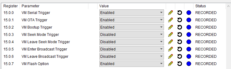
Each project can have different file extensions such as “.evc” and “.evi”. The “evc” are the files that possess the different functions whereas the“.evi” extension has all of the native functions combined. The native functions allows you to interact with the different registers, buffers and radio equipment. You can navigate throughout these files thanks to the tabs found at the top of the screen.
On top of the tabs, you will see the following buttons:
- Verify VM code for syntax errors
- Compile code and upload it to the selected radio
- Create a new project
- Open a project
- Add a file to the project
- Erase a VM code from a selected radio module
All projects are saved in the “Project” folder. Each radio in the radio list links to a VM project. It’s possible to have several radios linking to the same project. Therefore, when you edit a project, all radios link to the same project. Moreover, when a project is modified, all the radios that are linked to it are the ones that are affected by the source code modifications. This feature is particularly useful when deploying several identical sensors. It’s important to specify that each module must be programmed independently.
In order to program the VM code of a radio module, there are two possibilities. Either programming it via the serial port or “over the air”. To program via the serial port, you must be directly connected to a local node. To program it OTA, you must be connected locally to a gateway that will transmit the code via the mesh.
The following example demonstrates how to create a project and how to program the VM code from a radio.
- Go into the Code tab and click on the button
- Enter the name of the project “test_prog” and click on “ok”.
- For every node that will have this VM code, double click on it from the list of radios and modify the project so that it will be associated with the project “test_prog”.
For programming via a serial port
- Connect the application to the node via the serial port and an FTDI board.
- In the list of configured radio, the radio should be connected locally.
- Make sure that the correct radio is selected from the list of radios and click on
- The console at the bottom of the window should indicate that the programming is successful.
For OTA programming
- Connect the application to the mesh gateway of the serial port.
- Select the gateway in local from the list of radios
- Make sure that the programmed radio is synchronized to the mesh.
- Select the radio that you want to program from the list of radios, it should be in remote mode.
- Click on the button. The progress of the download should be displayed in the bottom console.
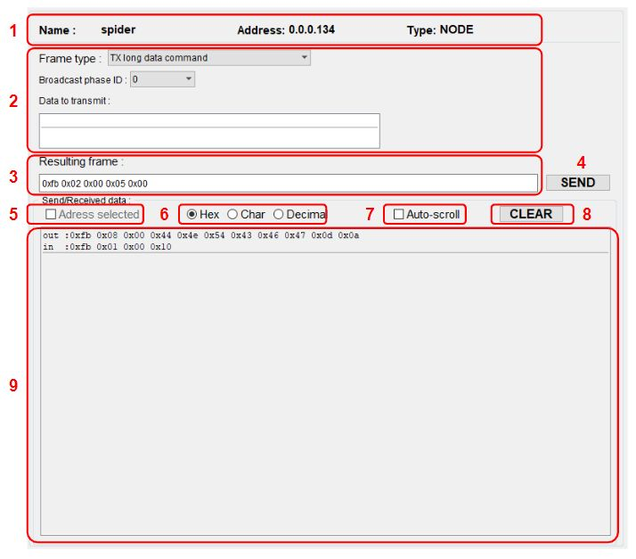
Console
The console is a tool used to view the received communication frames. It also offers a frame builder. Communication can be displayed in hexadecimal, ASCII or decimal format. All exchanges on the serial port between the radio module and the software are made visible in the
console tab.
The Console tab features:
- Selected radio module information
- Frame builder
- Transmissions in hexadecimal format
- Send transmission on the serial port button
- Address information
- Type of displayed data
- Auto-scroll console
- Clear console
- Console box
Under “frame type”, the VM execute command is frequently used in order to execute a VM script.